Hover via Three Point Touch

As a long time user of mouse and keyboard, a “touch only” interface makes me feel like I’m working with 7 fingers tied behind my back.

Hmm . . . . I guess I only say that because it sounds funny.  I’m not a touch typist.  Ten fingers never come into play.  I’m only working four “hunt and peck” fingers now, as I write this blog.  Given typing prowess like mine, an onscreen keyboard is not much of a hindrance.  What can cost me efficiency, however, is the method of selection, i.e., Touch.

I’ve owned a Surface RT for about three months and find the devise quite useful.  “Metro” and I have come to terms,  and I acknowledge the touch friendliness.  Be that as it may, my more critical tasks happen on the Desktop, where “touch only” hamstrings the effort.  We have been led to believe that the next MS Office release will be more touch centric.  Good news for everyone with modern screen, especially those of us using RT.  I suspect, though, that future “legacy” app releases will incorporate “touch” at varying rates, the time frame for some major applications extending beyond the lifespan of these early Windows Pro devises.   A main advantage for tablets – no peripherals needed – encounters a huge obstacle with imprecise pointing.  Adoption of these devises will be impeded.  This is my suggestion, and where those three, unfettered fingers come into play.

A standard two finger touch gesture is taken – Pan and “Pinch to Zoom” are too useful.  A time sensitive three point touch, though, should be available.  If thumb and forefinger are stationary for 250 milliseconds, and the middle finger taps the screen, a cursor should appear at midpoint of thumb and fore-.  Those two fingers can be moved, rotated, and/or spread apart while maintaining the cursor exactly at the middle.

This cursor now inherits all the “hover” capabilities of a standard Windows cursor, and the user has an unobstructed view.  Subsequent middle finger taps make selections.  A middle “tap and hold” reveals a “Right-Click” menu.  Removing all fingers returns the OS to a standard touch mode.

I included some graphics to illustrate the sequence.  The first set shows an interaction with AutoCAD, the later images show similar use with Excel.

AutoCAD

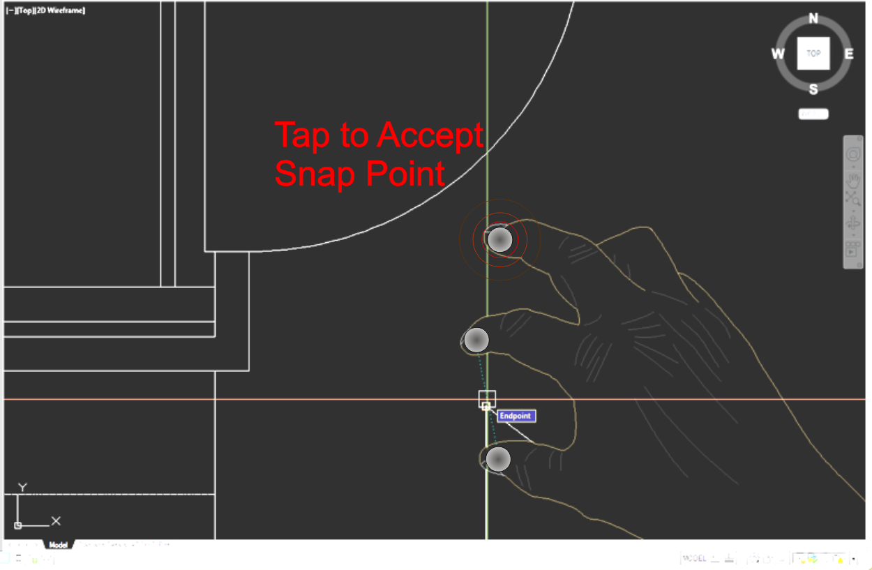
Hover is critical in CAD applications – to facilitate Object Snap features.  The image below shows a user with a cursor already acquired (in AutoCAD a point selection process turns the cursor into crosshairs) .  The start point for the Line uses a running osnap to select an existing endpoint.

AcadFirst

Mid way through the command the Cad operator uses the “Right-Click” feature to call the OSNAP Short-Cut menu.  The point acquisition process would be suspended, but the three finger gesture continues with arrow cursor to make a temporary snap selection (Perpendicular, for instance).

AcadMiddle

Now the Cad operator moves the aperture close to the arc, allowing AutoCAD’s to find the appropriate snap point, often well removed from the cursor.

AcadFinal

The command can be terminated here by removing all fingers, or, if line creation continues, point selection proceeds with the appropriate “rubber banding”.  The speed of multi point selection should approach that of mouse driven AutoCAD.  And, given that most tablets have at least 5 point touch capabilities, zoom/pan operations could be realized with two fingers of the opposite hand.

Excel

Excel doesn’t suffer to the same extent as AutoCAD, but touch does require more “sub-menu”ing to isolate the correct selection.  The standard windows cursor is more precise, thus eliminating the ambiguity inherent with a selection area  the size of a finger tip.

Here, the cursor has been acquired and moved over a UI element.  The “On Hover” event shows the tool tip which the OS locates opposite the hand location.

DragToPosition

A middle finger tap calls the next menu.  Repeat the process to create a sub-menu selection.

TepToSelect

Advertisement
Posted in AutoCAD, General

STSC_uvVectorMap Tutorial

This tutorial will demonstrate the use of the STSC_uvVectorMap command.  As I’ve mentioned in other tutorials, it is difficult to predict how some of my routines will be used.  For this demo I tried to create a fairly generic scenario, though I could easily see how the specifics would never be directly applicable.  That’s okay, as long as the demonstration offers guidance to whatever task the user does intend.

The objective of this scenario requires me to depict braided hose.   One way to do this would be via photorealistic rendering.  The scenario must contend with certain scalability and printing issues  (pen plotter compatibility) that lends itself towards a pure vector graphics solution.  I’ve got just the tool for the job.

I first create the construction geometry necessary for the curved cylindrical tube.

ConstructionGeom

The LOFT command uses the two circles as profiles, and the spline as the path.  The resultant surface serves as the base for the morphed texture pattern.

Extrusion

The STSC_uvVectorMap routine is a two stage command.  The UV parameter space of the cylinder needs to be transformed to 2D. The Ribbon/Plug-Ins/Vector Map/XYMap button calls the appropriate command (CPMAP).*

The 2D mapping will always be near the WCS origin.  If the drawing contains other, non-related geometry in that same area it may be advisable to freeze/hide that until the vector mapping operation is complete.

CallXYMap

The “Canvas” returned by the CPMAP procedure will be a block reference.  The rectangle in the block represents the full UV Parameter Interval associated with the surface.  A possibility exists that this interval extends beyond that of the picked surface due, perhaps, to a previous Trim/Boolean operation.  Trimmed edges will be included in the Canvas, so coordinating geometry placement should be possible.  The Canvas also includes data about the original surface. This data allows coordination for subsequent procedure calls.

Any of AutoCAD’s curve based entities can be mapped back to the 3D surface.  In this demo, I pre-HATCHed the appropriate sized rectangle with a pattern that resembles a braided sheath, then EXPLODEd that to standard lines.  I moved the group of lines back into position then initiated the CVPGLOBAL procedure by clicking the Ribbon/Plug-Ins/Vector Map/UVMap. *

CallProjector

The routines asks the user (me, in this case) to select the geometry to be mapped, then to select the Canvas.  Upon successful operation, the Canvas should be erased from the drawing, and facsimiles of the 2D geometry mapped back to the 3D surface.

A PDF of the final product.

uvVectorMapTute_BraidedTube

The Chronicle video demonstrates much of the procedures described here.

https://chronicle.autodesk.com/Main/Details/a3afe1be-968d-421c-81f6-167c375abfca

* I apologize for this confusion with naming.  If needed, I might modify the naming convention on the procedures next update.

Posted in AutoCAD

More wishing for Windows RT Surface

At the end of the day, these blades are about maximizing screen real estate and offering an efficient, haptic UI.  In much the same fashion that a physical qwerty pad outperforms the on screen keyboard for word processing, blades would facilitate other extreme user input endeavors.

I think Microsoft could leverage Windows RT further on this front.

I’m a big fan of multiple monitors on my desktop.  Many of the Application I use have extremely complex UIs.  So, when using AutoCAD for example, I can transfer some of the UI elements onto a second monitor to maximize the drawing area on the first.  Without the second monitor, the various screen elements encroach upon each other.

This situation can become even more cluttered as other applications are opened, each with its own UI, each potentially used in continuous support of each other.

The processor and memory resources of the Surface Pro could meet the challenge, but the screen will be the limiting factor.  Used as I described above, the necessary screen changes would be strobe like.  Docking into an additional monitor would be quite gratifying.

What if Windows RT allowed the devise to be used as a second monitor?  It could not actually host any of the x86/x64 applications, as the hardware specs to not allow it, but it could certainly contend with UI elements.

An Autodesk app could be fired up on the Windows RT devise to allow me to host the UI from AutoCAD – currently running on my desktop or Surface Pro.   Autodesk may even provide a blade for AutoCAD or Inventor, or all of their other applications (similarly, Microsoft with Office-Visual Studio , Adobe . . .).  The Blade serves as the constant UI, the screen of the Windows RT devise would be the volatile, context sensitive UI.

Both Windows and Windows RT communicate so that the RT updates the UI based on which Application is active on the Pro version (obviously, the blade wouldn’t change but the RT screen could).

Say this were all possible, now the additional cost of the Surface 2 can be adjusted to consider the saving as would be incurred with the purchase of a second monitor.   This efficient package can easily follow the user around from office to home or any other place where a second monitor would be useful.

Posted in AutoCAD, General

Windows RT wish list

Hopefully, Microsoft will distribute a Software DevelopersKit (SDK) and incorporate Blades, Keys and Touchpads into the Toolbox of some soon to be released version of Visual Studio (VS).  Creating a custom blade should not be much different from designing WinForms. 

Perhaps a little more functionality could be added to VS to allow the automatic generation of vector graphics – ready to send to a SilkScreen maker.  That way, when Microsoft delivers the blank blades, $45 unit price when purchased in bulk, the Developer can get the graphics applied based on the current weeks orders for each particular Bladeware app.

Posted in AutoCAD, General

Real work with Windows RT Surface

Did Microsoft just reveal RT’s killer app?  Not the typical App Store app.  A combination of hardware and software – can’t use firmware, as that term already has implications, – perhaps it will be called  “Bladeware”.

http://www.citeworld.com/tablets/224…surface-blades

If I’m interpreting correctly there are numerous sensors below the touchpad surface that put the whole expanse up for grabs.  Is it just a matter of a printed overlay and a custom calibrated app.

It might make custom blades extremely affordable.  Say something like this to simplify CAD input for piping, complex masonry/tile work, surveying . . . .
General

Or this to allow patient monitoring without interfering the current image on screen.

Hospital

Seems like a lot of possibilities for field work.

Posted in AutoCAD, General

STSC_HeightMap Tutorial

Many of the routine I’ve published on Autodesk-Apps will not appeal to “run of the mill” CAD users.  I don’t find that bothersome, though, because they already have numerous developers vying for their attention.  The users out at the fringe – working with AutoCAD in a way that has others telling them that they are using the wrong program – are more likely to see the value in my routines.  You are the guys that I relate to.  Of course, you are also the most difficult to predict “what the hell” it is that you are actually doing with AutoCAD –  or anything else for that matter.

Consequently, the end result of this tutorial may seem contrived.  I tried to make the scenario somewhat general, for fringe dwellers anyway, but I doubt that the specifics would ever be generally useful.

The purpose of the tutorial is to demonstrate some techniques leveraging raster image manipulation tools to produce a base image for my STSC_HeightMap routine; with the ultimate goal of creating a 3D surface that would be extremely difficult to produce any other way.

The scenario:

Create a reasonably accurate model of ripple interference.

First step:

I’ll use AutoCAD to create a single radial ripple pattern.  The colors used for successive ripples diminish proportionally with distance from the center:

http://a360.co/15CtZnx

InAutoCAD

Second step:

Using either a Publish to Web JPG/PNG or even just a PrintScreen key press I created an importable raster file ready for image manipulation.  In my case I brought the image into Corel PhotoPaint.  I suspect the other players in the image manipulation industry have similar functions.

Image Manipulation steps:

The first thing I did was to apply a Gaussian blur.  This softens the edges to produce a more Natural/Sinusoidal transition from one color to the next.

PostBlur

A copy and Paste As Object operation gave me another exact copy aligned on top of the original.

Interference of wave patterns always produce constructive and destructive intersections.  To best replicate this property I used the “Multiply” merge mode.  This tell PhotoPaint to combine the images such that two aligned dark pixels get darker, two light pixels get lighter.  See this short animation captured while I moved one image relative to the other:

http://a360.co/15Cuazc

Eventually, I placed three copies into an arrangement that had some interesting interference patterns.

FinalTriInterfere2

In the final step I returned to AutoCAD and applied the displacement to a regular surface:

https://chronicle.autodesk.com/Main/Details/da1ab04e-55fa-4aa5-aebd-8ae48928f219

I’m not sure what the surface is, or why I would have needed it, but the process for creating it was not too bad.

http://a360.co/198zXNR

Posted in Uncategorized

Yet Another Focus

AutoCAD’s evolution fascinates me.  Arguably, still the top computer aided drafting package available.  The tool set allows the documentation of mundane shop/field drawing up to multi sheet, legally binding plan sets.  AutoCAD is the essence of Graphical/Textural communication.

Users of the software tend to be the most prolific authors of digital data.  Not many jobs call for 8 hours a day, 5 days a week, near 52 weeks a year of high intensity button clicking.  And it’s all about communication – clear, concise, accurate, and, ofttimes, immediate.

As a frequent practitioner of that type of intensity, I really see the benefits of saved button clicks.  There are times, deadlines looming, when a missed button click causes palpable anxiety.  Even with complete certainty that a mere few second readjust will correct the situation, the anguish of lost efficiency stabs home.  I perceive it as an incursion in the thought process.  It’s an unseen speed bump, very disruptive at full throttle.  In this analogy “speed bumps” have no redeeming value as I’m not likely to run over some hapless pedestrian.

I don’t think I’m alone in this.  Anyone dealing with AutoCAD regularly has a vast assortment of tricks to speed up processes and eliminate redoes.

Many of those users have also made a habit of reading the various Blogs, Newsgroups, Forums dedicated to AutoCAD.   I’m a reader/member in just about all of them.  And all of them have offered tricks and procedures to save at least few button clicks per hour.   I’m extremely grateful.

One of my other intentions for this blog is to present some tips and tricks that I have not seen presented elsewhere . . . . or, at least not presented well enough to have disseminated to all that would find them useful.

Most of the tips will be in the form of command macro’s.  As restricted as that process may be, it still provides many opportunities to avoid  incursions.

Posted in AutoCAD

Alternate Focus

I intend to dedicate a portion of this blog’s topic space to the use of tablets in Computer Aided Design.   Despite some of Autodesk’s offerings (AutoCAD WS, Sketchbook) I’d say this form factor is still in the formative years.  I’d love to hear the multitude of ideas on how best to incorporate tablets into CAD.

My own personal bias will no doubt be exposed.  I have a sizable investment in the Windows ecosystem, so I didn’t consider buying a devise until that system’s emergence.  I currently have a Windows Surface RT.  I’m absolutely certain that the other camps (iOS, Android) offer extremely good products.  If I had a little extra cash lying about I would buy an example of each of them.  I’d probably be quite impressed by the polish.   This type of tech benefits from every week of it’s existence.  Windows has a late start; I’m betting, though, they can still get into the game.

I guess Windows RT’s first milestone – at least as far as my needs are concerned – will be to show staying power enough to coax Autodesk into porting their AutoCAD 360 app.  The web format will do in the meantime; the full up app would demonstrate some faith.

Posted in AutoCAD, General

Welcome to my Blog

Hello visitors,

Welcome to my blog.  While I expect future postings to be multi-purpose (perhaps to the point of unstructured), the primary role of this blog is to have more in-depth communication with users of my Exchange App routines.

Do not hesitate to leave a comment if issues have arisen with any of the apps, or if you would like to make suggestions for further updates.

Likewise, if you are an AutoCAD developer and are curious about the mechanisms employed by my routines, please comment.

I’m glad you stopped by,

Sean Tessier

Posted in AutoCAD, Uncategorized